Basic Logic Gates
A logic gate is an electronic circuit/device which
makes the logical decisions. To arrive at this decisions, the most common logic
gates used are OR, AND, and NOT.
Logic gates have one or more inputs and only one
output. The output is active only for certain input combinations. Logic gates
are the building blocks of any digital circuit. Logic gates are also called
switches. With the advent of integrated circuits, switches have been replaced
by TTL (Transistor Transistor Logic) circuits and CMOS circuits.
The NOT Gate, or Inverter
The inverter is always has exactly one input as well as one output.
Whatever logical state is applied to the input, the opposite state will appear
at the output.
Truth table and symbol of the NOT gate is
shown in the figure below.
The OR Gate
The OR gate performs logical addition, commonly known
as OR function. The OR gate has two or more inputs and single output. The
output of OR gate is HIGH only when any one of its inputs are HIGH (even if one
input is HIGH, Output will be HIGH).
If X and Y are two inputs, then output F can be
represented mathematically as Y = A+B. Here plus
sign (+) denotes the OR operation. Truth table and symbol of the OR gate is
shown in the figure below.
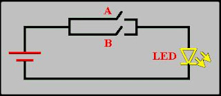
In the figure, A and B are two
switches which have been connected in parallel, and this is connected in series
with the load LED and source battery. When both switches are open, current does
not flow to LED, but when any switch is closed then current flows.
If A = 0 and B = 0, then the LED turn OFF (0/LOW).
If A = 0 and B = 1, then the LED turn ON (1/HIGH).
If A = 1 and B = 0, then the LED turn ON
If A = 1 and B = 1, then the LED turn ON
The AND Gate
The AND gate performs logical multiplication, commonly
known as AND function. The AND gate has two or more inputs and single output.
The output of AND gate is HIGH only when all its inputs are HIGH (i.e. even if
one input is LOW, Output will be LOW).
If X and Y are two inputs, then output F can be represented mathematically
as Y = A.B, Here dot
(.) denotes the AND operation. Truth table and symbol of the AND gate is shown
in the figure below.
In the figure below, A and B are two
switches which have been connected in series (or just cascaded) with the load
LED and source battery. When both switches are closed, current flows to LED.
If A = 0 and B = 0, then the LED turn OFF (0/LOW).
If A = 0 and B = 1, then the LED turn OFF
If A = 1 and B = 0, then the LED turn OFF
If A = 1 and B = 1, then the LED turn ON


